

| DATA SHEET |
| Professional Grade Resistors Produced by Fully Automated Process |
| Tin Plated Copper Wire Ensures Excellent Solderability |
| Solvent Proof Colour Code Marketing |
| Standard Tolerance as 0.1%, 1%, 2%, & 5% |
| Conforms to JSS 50401-RFGP-2 |
| ERTL, CACT, ITI Approved |
| Very Low TCR as 5ppm also available |
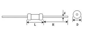
| Style | Power Resistance at 70°C | Dimensions in mm | Max Working Voltage (V) | Max Overload Voltage (V) | Rasistance Range | |||
| L | D | d | H (Min) | |||||
| KMR-16 | 0.16W | 3.7±0.4 | 1.8±0.2 | 0.45±0.02 | 28 | 200 | 400 | 1Ω-10M |
| KMR 25M | 0.25W | 3.7±0.4 | 1.8±0.2 | 0.45±0.02 | 28 | 250 | 500 | 1Ω-1M |
| KMR 25 | 0.25W | 6.5±0.5 | 2.3±0.2 | 0.45±0.02 | 27 | 250 | 500 | 1Ω-10M |
| KMR 50M | 0.5W | 6.5±0.5 | 2.3±0.2 | 0.45±0.02 | 27 | 350 | 700 | 1Ω-10M |
| KMR 50 | 0.5W | 9±1 | 3.4±0.5 | 0.52±0.02 | 25 | 350 | 700 | 1Ω-10M |
| KMR 100 | 1W | 12±1 | 5.0±0.5 | 0.60±0.02 | 30 | 500 | 1000 | 1Ω-10M |
| KMR 200 | 2W | 16±1 | 5.5±0.5 | 0.68±0.03 | 28 | 500 | 1000 | 1Ω-10M |
| *(Rated Continuous Working Voltage); ?P X R or Maximum Working Voltage whichever is low. | ||||||||
| ** Maximum Overload Voltage: RCWC & 2.5 for 5 sec or Maximum overloads voltage whichever is low. | ||||||||
| Characteristics | Test Methods | Limits | ||||
| D C Resistance | Resistors are tested with standard specified voltages for its Ohmic values to check the specified tolerance. | The Resistors shall be within specified tolerance limits. | ||||
| Short Time Overload | The Resistors shall be subjected to 2.5 times the Rated Voltage or Maximum overload voltage (whichever is low) for a duration of 5 secs. | ? R % = ± 0.5% (+ 0.05 ?) | ||||
| Temp - Coefficient | The Resistors value shall be checked at 2 temp. i.e. one At Ambient & the final at Amb + 100? C. The TCR is then Calculated as :
|
PPM | ||||
| 25 PPM /?C | ||||||
| 50 PPM /?C | ||||||
| 100 PPM /?C | ||||||
| 200 PPM / ?C | ||||||
| Rated Load | A Rated Continuous Working Voltage or Maximum Wkg. Voltage whichever less shall be applied to the resistors for a duration of 2 Hrs. | ? R % = ± 0.5% Max | ||||
| Solderability | A solder bath is maintained at 230? C. The specimen leads are immersed in the bath & withdrawn within 3 secs. A suitable flux is used during the test. | A fresh solder shall cover the specimen leads by Min. 95% coverage. | ||||
| Resistance to solder heat | A solder bath is maintained at 350? C. The specimen leads are subjected to the bath for a duration of 10 secs. | ? R % = ± 1 % Max | ||||
| Resistance to Solvents | The specimen shall be subjected to IPA for duration of 1 min. 10 strokes of hard brush shall be applied. The test shall be conducted 3 times. | The colour code marking shall remain legible. | ||||
| Die-electric Strength | A foil is wrapped around the specimen body. A voltage of 300 V @ 0.5 ma shall be applied between both the terminals of the specimen for a duration of 1 min. | There shall be no flash over or break down. | ||||
| Terminal Strength | Pull Test: The resistors leads shall be pulled using 5 N force Bend Test: The resistor leads are bend through 180? three times. | There shall be no damage. | ||||
| Load Life | The specimen shall be subjected to an ambient of 70?C for duration of 1000 Hrs. The specimen shall also be loaded for full power dissipation. The duty cycle shall be 1½ Hr. On ½ Hr. Off. | ? R % = ± 2 % Max | ||||
| Steady State Humidity | The shall be subjected to an amb. Of 40?C with RH as 95%, for a duration of 56 days. A small DC voltage shall be so applied that the specimen shall dissipate 1% of the rated power. | ? R % = ± 2 % Max | ||||